Ultrathin Oscillating Heat Pipes: Part 1 Limits of Operation
By Dr. Corey Wilson, Director of R&D, and and Joe Boswell, CEO of ThermAvant Technologies
Many customers wish to maximize packing density of opto-electrical and RF components onto increasingly thin, tightly pitched printed circuit board (PCB) assemblies. This leads to increased heat fluxes and less overall size and space for heat removal - and, in turn, to the development of sub-1 mm thick, ultrathin heat spreaders and transporters. Status quo ultrathin thermal devices include solid-state graphite heat spreaders; or two-phase vapor chambers and heat pipes [1, 2], this study discusses the latter - see below.

Here at ThermAvant Tech have recently developed a third ultrathin thermal device using the Oscillating Heat Pipe (OHP) technology - see below.

This is a two-part study to investigate how ultrathin OHPs compare with heat pipes and vapor chambers. This first release focuses on theoretical limits of operation and published results of ultrathin vapor chambers and heat pipes. A second, follow-on paper will present empirical results of an ultrathin OHP solution vis-a-vis findings herein.
Evaluation Method: Form Factor, Boundary Conditions, Models and Data Sources
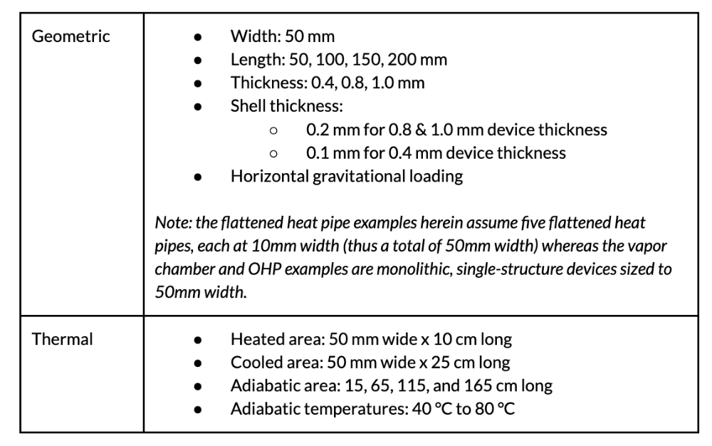
First, we used a standard 50 mm width for the ultrathin thermal devices and standard heating-cooling condition with a heat source on one end (50 mm x 10 mm) and a larger heat sink on the other end (50 mm x 25 mm). We varied thermal device thicknesses from 1 mm to 0.8 mm to 0.4 mm and device lengths from 50 mm to 200 mm. We set the adiabatic temperatures at 60 deg-C for all cases. See Appendix A.

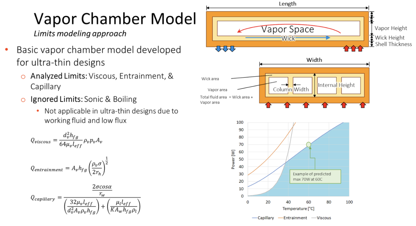
Then, we compiled theoretical thermal power limits for high-performance ultrathin vapor chambers and flattened heat pipes [Appendices B and C] when operating in such a condition. Models were based on the limits of operation for wick-based vapor chambers, namely viscous, entrainment and capillary limits. The model for flattened heat pipes’ biporous wick structures required adjustments to closer match empirical data.
Separately, OHP devices were modeled using ThermAvant Tech’s in-house OHP limits model [3]. OHPs were modeled with ammonia as working fluid; vapor chambers and heat pipes with water. Appendix D shows the 0.4 mm, 0.8 mm and 1.0 mm thick OHP limits with alternative working fluids.
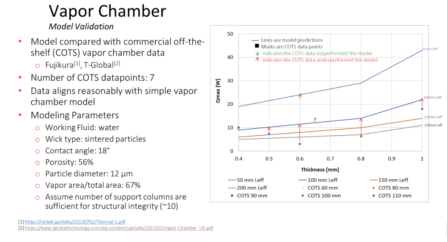
Finally, we gathered COTS vapor chambers’ and flattened heat pipes’ published maximum powers [1, 2] to evaluate next to the models’ predictions. Notably, there is relatively little COTS data, especially for ultrathin flattened heat pipes less than 0.8mm thick – or for ultrathin vapor chambers more than 100mm long.
Results and Analysis
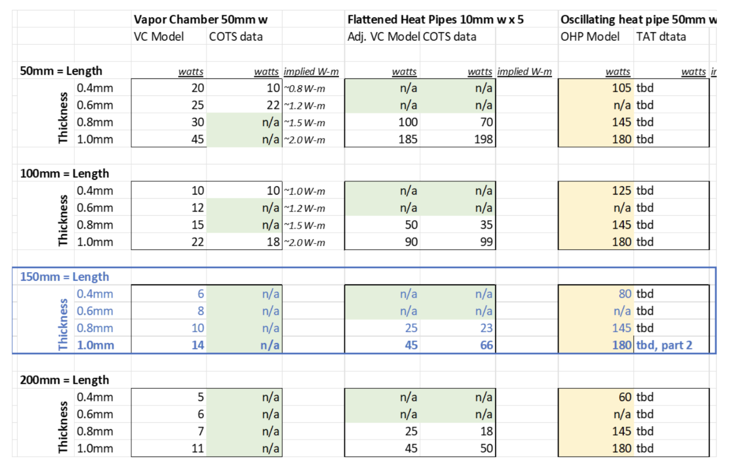
The results are summarized in the charts below.

Referring to the leftmost graph above, the models predict the OHP to have the highest theoretical power limits as lengths exceed 50mm. This is due to the relatively low, uniform viscous losses in the “wickless” OHP, whereas wick-based devices’ capillary limits quickly impact heat transfer rates as lengths exceed 50 mm.
Referring to the rightmost graph above, the models also predict that OHPs at 0.4 mm thickness and above have the highest theoretical power limits. But, at <0.4mm OHPs are difficult to model due limited cross-sectional area and sensitivity viscous and other losses. Thus, ultra-thin vapor chambers may be preferable at thicknesses <0.4 mm, though more research is needed into OHPs and flattened heat pipes at this scale.
The only exception to the OHPs’ preferable upper power limits per this analysis, is that the 50 mm long, 1 mm thick array of flattened heat pipes (5 heat pipes, each 10mm wide) have an upper power limit of approx 200 W capacity (based on 2 W-m per heat pipe), whereas the 50 mm long, 1 mm thick OHP has 180 W capacity; and vapor chambers’ capacity is theoretically 45 W capacity. Thus, at distances of 50mm and thicknesses of 1mm ultra-thin flattened heat pipes may be preferable to vapor chambers or OHPs.
Conclusions
Referring to the table below, sub-millimeter thick OHPs demonstrate significant potential for high heat load space-constrained applications. They transfer higher heat loads than vapor chambers and flat heat pipes across most thicknesses and transport lengths. This new category of ultrathin can enable system designs not previously possible.
Experiments of ThermAvant Tech’s 150 mm long x 50mm wide x 1 mm thick aluminum OHP have already started. The second paper in this series will disclose its results and compare to the findings herein. And this is just the beginning, as visible by the scarcity of COTS data in the table below, there is much work to be done in the world of ultrathin thermal devices!
References
[1] Randeep Singh, “Fujikura Thermal Technology Overview” [Online]. Available: https://rd.kek.jp/slides/20130702/Thermal-1.pdf.
[2] T-Global, 2023, “Vapor Chamber” [Online]. Available: https://www.tglobaltechnology.com/wp-content/uploads/2023/01/Vapor-Chamber_UK.pdf.
[3] Drolen, B. L., and Smoot, C. D., 2017, “Performance Limits of Oscillating Heat Pipes: Theory and Validation,” Journal of Thermophysics and Heat Transfer, 31(4), pp. 920–936.
Appendix A: Geometric and thermal boundary conditions
Appendix B: Ultrathin vapor chamber model and validation
Appendix C: Ultrathin heat pipe model and validation
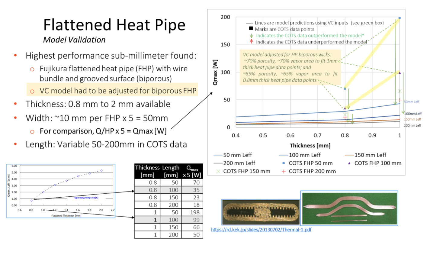
Note chart above is for five flattened heat pipes (each 10mm wide) to create a 50mm wide device.
Appendix D: Ultrathin oscillating heat pipe limits models using different fluids
The Limits of Operation for the OHP are different from a vapor chamber; these limits are discussed in Reference 3. The following table shows the Limits of Operation for ultrathin OHPs. Ammonia is viable for OHPs as thin as 0.4 mm, however butane and R1233zd(E) have limited transport capacity below 1 mm and are likely non-viable at 0.4 mm and below.
Table below provides Limits of Operation for a 200 mm long OHP at 0.4 mm, 0.8mm and 1 mm thicknesses with various working fluids (Ammonia, Butane and R1233zd(E))
